
MEASUREMENT FUNDAMENTALS
Eddy current sensor working principle vs. inductive switches
A high-frequency coil generates an alternating magnetic field. A conductive target develops eddy currents that change the coil response; the conditioner converts that change into a calibrated distance signal.
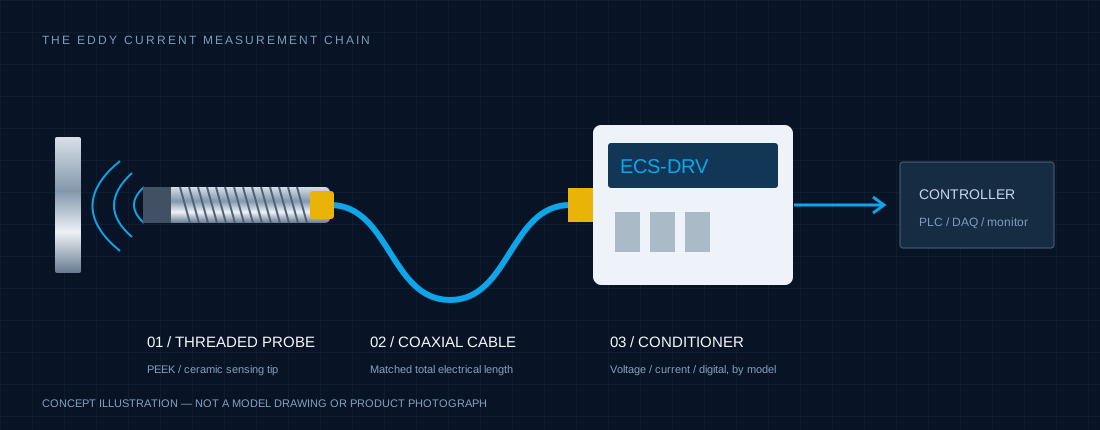
Measure displacement within a calibrated working gap.
The useful linear range starts at a defined stand-off. Resolution, linearity, repeatability and absolute accuracy describe different limits. Quote them with bandwidth, target and temperature conditions; do not use a resolution number as an accuracy guarantee.
| Decision | Eddy current displacement system | Standard inductive proximity switch |
|---|---|---|
| Measurement | Continuous distance or dynamic motion | Target present / absent |
| Output | Calibrated voltage, current or digital distance | Discrete ON / OFF |
| Specify | Range, resolution at bandwidth, target and calibration | Switching distance, hysteresis and switching frequency |
Analog inductive distance sensors also exist. Compare the actual measurement principle and performance, rather than the category name alone.
Oil and coolant still need application-specific checks.
Many non-conductive contaminants have less influence than they would on an optical path. Conductive liquids, metallic debris, target-temperature changes and coatings can still alter the signal. Verify the actual coolant and installation instead of assuming universal immunity.
Turn RPM into the frequency the sensor must resolve.
Blade-passing frequency = RPM × blade count ÷ 60. For 200,000 RPM and 12 blades, the result is 40,000 Hz. Confirm rise time, filtering, pulse threshold and signal-to-noise margin in addition to nominal bandwidth.
Primary engineering references
These sources explain the measurement technology and original systems; they do not establish ECS performance or cross-brand compatibility.
Send your configuration for review ↗