
SENSOR SYSTEMS / COMPONENTS & ACCESSORIES
Eddy current probes, extension cables & signal conditioners
Specify a complete measurement chain or identify the individual part you need. Start with the target, original component labels and the signal your controller receives.
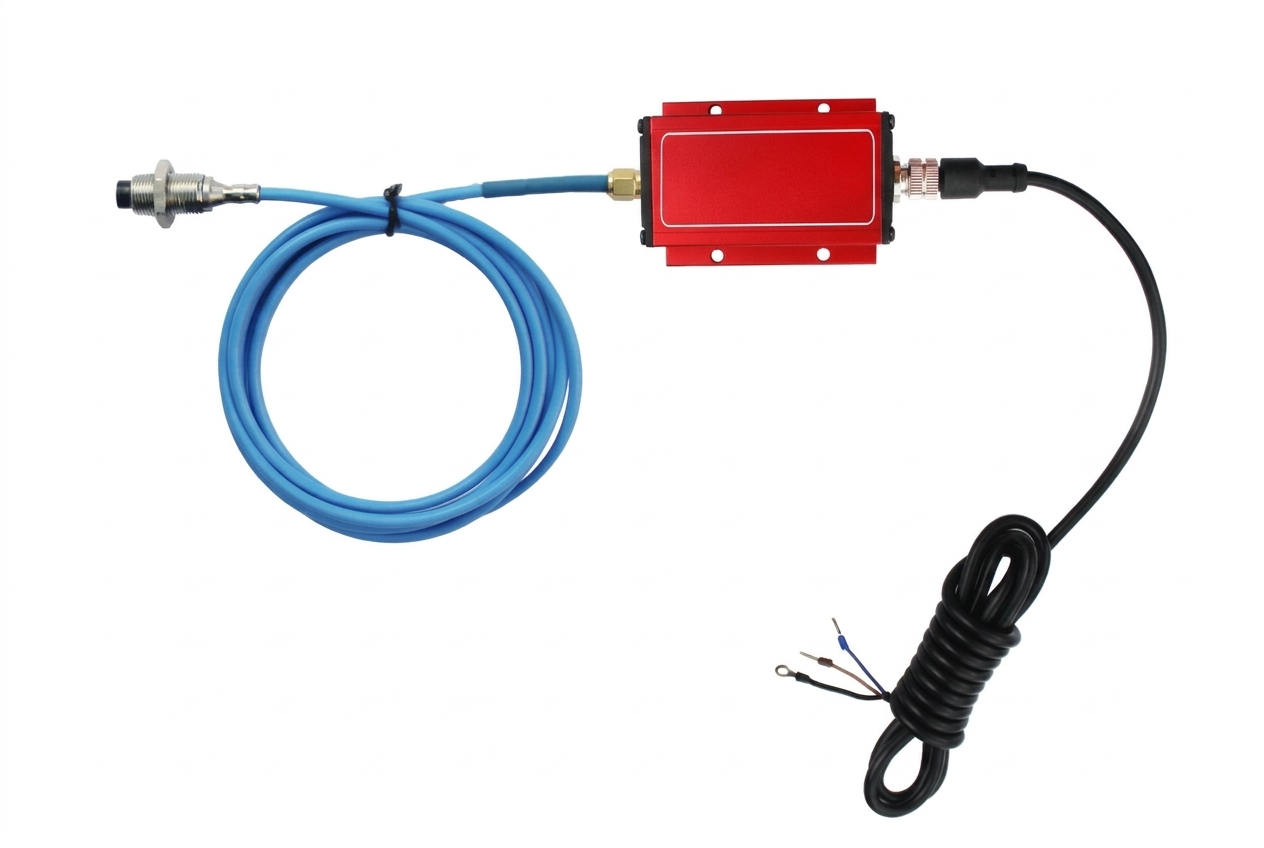
FROM SENSING FACE TO MACHINE INPUT
Order the part that closes the measurement chain.
| Item | What defines the configuration |
|---|---|
| Probe / sensing head | Thread or flange, body and unthreaded lengths, cable exit, target and required gap. |
| Extension cable | Exact references, nominal electrical length, connector pair, armor and routing environment. |
| Signal conditioner / driver | Matched probe system, supply polarity, output definition, mounting and controller input. |
| Gap / vibration transmitter | Gap or vibration quantity, range, unit, filtering and loop/interface requirements. |
| Mounting bracket / adapter | Housing drawing, adjustment access, thread, side clearance and environmental sealing scope. |
| Static-gap calibration fixture | Target grade and shape, travel and reference-instrument requirements; agree the test scope. |
For a replacement, send the complete original suffixes and labels before deciding which parts to retain. For a new design, provide the target, gap interval, available mounting space and receiving input. Matching a connector or thread is one part of this review.
Choose the output by the quantity you want to measure.
| Signal path | Quantity | Information to confirm |
|---|---|---|
| Raw proximity voltage | DC gap and dynamic voltage | Confirm sign, scale, operating gap, supply and monitor input. |
| Position voltage | Continuous displacement | Confirm voltage span, reference ground, bandwidth and controller input. |
| Gap current | A defined gap interval | Specify current span and the two physical gap endpoints. |
| Vibration-severity current | A defined vibration quantity | State displacement/velocity quantity, units, detector and frequency band. |
| Digital measurement | Configured displacement data | Confirm protocol, update rate, filter and host interface. |
Include the receiving monitor or PLC input diagram. A gap transmitter and a vibration-severity transmitter need different physical endpoints, units and signal processing. Ask for supply polarity, signal reference and the approved pinout for the proposed assembly.
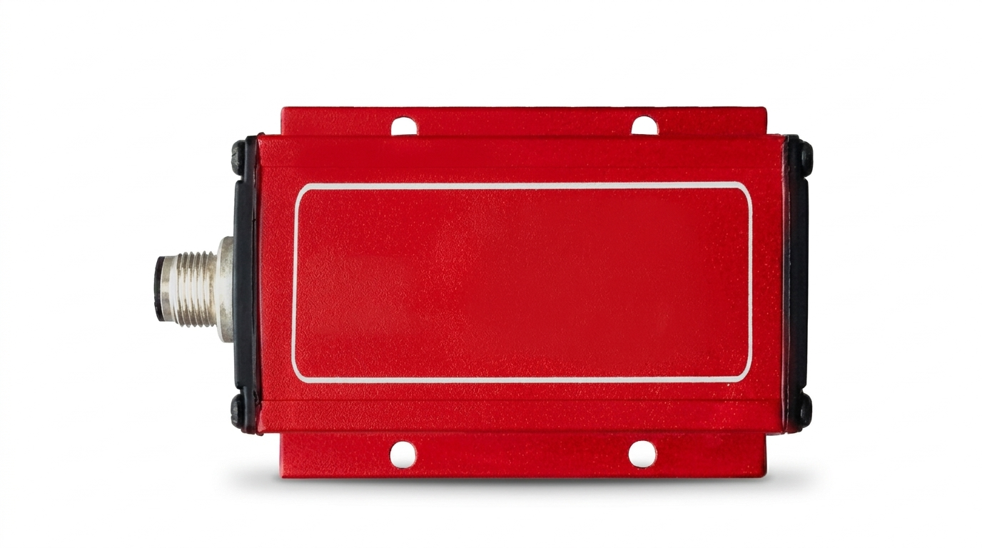
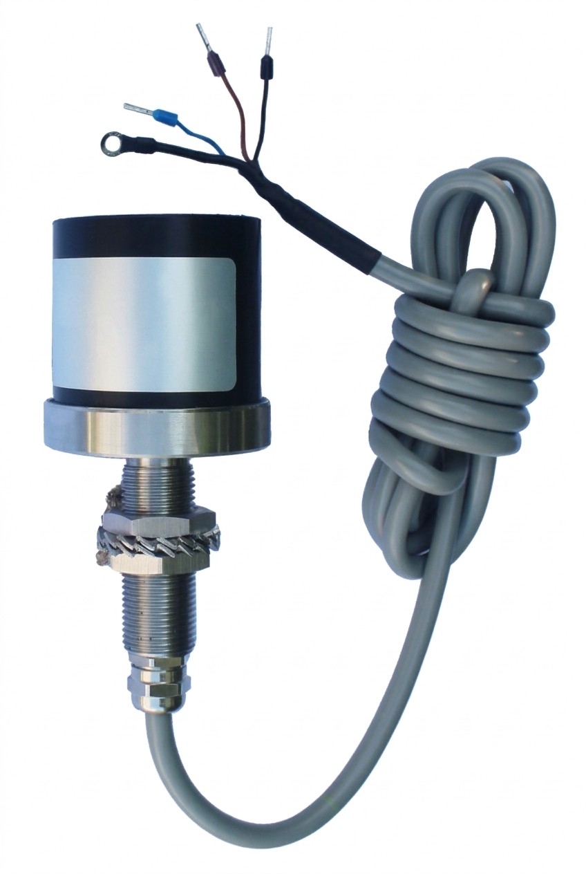
Keep nominal cable length, routing and sealing separate.
Record the integral probe-cable and extension labels, then compare their sum with the conditioner system-length label. The optional checker in the request below retains all three values. A nominal match checks arithmetic; the exact component pairing and transfer curve still need confirmation.
Specify connector access and the route through the machine. Stainless armor protects a cable mechanically; sealing, fluid exposure, allowable bend radius and transition temperature require their own assembly details. Provide a cable-route drawing when access or movement is restricted.
Original-system background: Baker Hughes 141194, extension-cable ordering information. Use the exact selected system’s installation instructions.
Use the bracket and fixture for a defined job.
A through-housing adapter should provide the required adjustment travel and mounting access. Send the thread, housing thickness, recess and side-clearance drawing. Confirm any electrical isolation or environmental sealing requirement rather than inferring it from the bracket’s appearance.
A static-gap micrometer fixture checks a transfer curve over an agreed range on a representative target. Define the reference instrument and uncertainty required. Dynamic vibration response, speed pulses and thermal behavior need separate test conditions.
Review target material, mounting and calibration inputs →
| Decision | Eddy current displacement system | Standard inductive proximity switch |
|---|---|---|
| Measurement | Continuous distance or dynamic motion | Target present / absent |
| Output | Calibrated voltage, current or digital distance | Discrete ON / OFF |
| Specify | Range, resolution at bandwidth, target and calibration | Switching distance, hysteresis and switching frequency |
Analog inductive distance sensors also exist. Compare the actual measurement principle and performance, rather than the category name alone.
Before ordering a probe, cable or driver separately
Can I extend the cable to reach the cabinet?
Send the existing labels and proposed route. A tuned probe/cable/conditioner assembly has configured nominal lengths and electrical characteristics. Agree a matched configuration before changing the lead or extension.
Which mounting and cable documents should I send?
Include the housing and target drawing, probe insertion direction, adjustment access, connector clearance, bend route and temperature zones. State what can be changed on the machine.
Can the same request include spare parts and a complete system?
Yes. Select the parts below and state the quantity for each item in notes. Identify which existing components would be retained and which assembly needs a fresh calibration review.
ECS / COMPONENT CONFIGURATION