
SENSOR SYSTEMS / SPINDLE ENGINEERING
Spindle thermal growth & runout measurement
For spindle thermal growth measurement, define the reference before selecting an eddy current spindle sensor. Separate axial growth, radial motion and temperature, then specify the gap envelope and the signal your CNC or acquisition system needs.
FIRST DECISION / MEASURED QUANTITY
A changing gap is meaningful only with an axis and reference.
| Task | Probe and target relationship | What to specify |
|---|---|---|
| Axial thermal growth | A stationary probe faces a shoulder or suitable ring surface along Z. The gap changes relative to the sensor support. | Cold gap, signed warm displacement, support reference and whether the required result is ring motion or tool-tip position. |
| Radial apparent runout | A radial probe views the rotating cylindrical surface. Geometry, motion and electrical runout contribute to the trace. | Target diameter/finish/material, speed, retained frequency content and the independent method used to evaluate the result. |
| Temperature reference | A separate temperature channel describes the location where that sensor is installed. | Sensor location, calibration, units and controller input. Probe-body temperature is not automatically shaft or tool temperature. |
For original-system context, Micro-Epsilon describes SGS4701 measurement at a spindle ring with a separate temperature output. An ECS review must establish its own geometry, signals and evidence.
ROTATING TARGET / MATERIAL UNIFORMITY
Resolve electrical runout before calling a trace mechanical error.
Local conductivity and magnetic-property variation can appear as displacement even after calibration on the same nominal alloy. Heat treatment, surface processing and residual magnetism belong in the target review.
The Professional Instruments / Lion Precision electrical-runout study explains this mechanism. Material calibration does not remove every circumferential variation.
Provide the actual sensing track or a representative target. Agree a comparison method appropriate to the required error level. A slow-roll record may characterize repeatable content, but subtracting it does not automatically isolate bearing error motion or validate a high-speed trace.
Reserve gap for the build, the warm spindle and the sensor support.
Total linear span is not the travel available on either side of your chosen cold gap. Review the nearest and farthest target positions, including assembly tolerance, expected motion and temperature effects.
- Target and mounting
- Identify shoulder width or shaft diameter, material, thickness, probe axis, nearby metal, side clearance and adjacent probes. Show bracket stiffness and the reference to the spindle housing on the drawing.
- Temperature by component
- State probe, target, cable, bracket, conditioner and coolant conditions. Mounting expansion can change the measured gap; target response and sensor zero/gain may also change with temperature.
- Acceptance quantity
- Specify the permitted error at the agreed gap, temperature and bandwidth. Resolution, repeatability, static linearity and tool-tip positioning error require different evidence.
The Kaman inductive measurement handbook, sections 4.2 and 5.5, distinguishes thermal zero and sensitivity effects. Its product-specific limits are not ECS ratings.
Include the gap and thermal cycle ↗DYNAMIC CONTENT / RPM IS NOT BANDWIDTH
Choose retained orders before choosing filters and sampling.
Rotational frequency is RPM ÷ 60. As an arithmetic example, 24,000 RPM gives 400 Hz at one revolution per cycle; the fifth order is 2,000 Hz. These frequencies describe requested signal content, not a demonstrated ECS response.
Slow axial trend
Define the warm-up time scale and any transient motion that must remain visible. Agree averaging and logging intervals without hiding the changes under review.
Radial waveform
State speed range, orders and peak/RMS/peak-to-peak convention. Request amplitude and phase response across the retained band; one bandwidth number is insufficient.
Acquisition chain
Specify the input card, anti-alias filter, sample rate and channel timing. An analog sensor output is not a promise of an alias-free sampled waveform.
SIGNAL HANDOFF / ENGINEERED UNITS
Bring the displacement scale all the way to the CNC input.
- 01 / Target gapAxis, support reference, material and operating envelope
- 02 / Matched chainProbe, cable and conditioner; signed scale and valid output span
- 03 / Input channelSupply/common, pinout, units, filtering, timing and fault behavior
- 04 / Machine validationObserve first; machine owner validates any compensation mapping
Confirm whether displacement and temperature are separate outputs, how the controller converts volts or current to engineering units, and which sign represents approach. Do not connect an original pinout or reuse its scale solely because a connector fits.
Embedded or external mounting?
An embedded request needs a spindle section, target surface, sensor pocket, cable route and conditioner space. An external bracket adds its own stiffness, thermal path and access constraints.
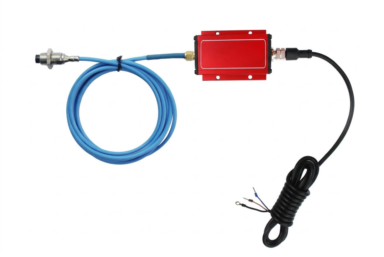
List the complete electrical assembly and connector variants. Request dimensions and the matching calibration before choosing individual replacement parts.
Review probes, cables and conditioners →Agree a cold, warm and cooldown comparison before acceptance.
Speed changes can also produce centrifugal or load-dependent movement. Keep speed and load conditions comparable when interpreting thermal trends; a warm-up gap trace alone does not isolate thermal growth.
- Record the cold reference. Identify the installed assembly, target track, gap, sensor support, controller scale and independent reference method.
- Define the duty cycle. Agree speed stages, dwell/end-point criteria, spindle load, coolant conditions and temperature locations with the machine owner.
- Log the same channels together. Retain raw gap, processed displacement, RPM, elapsed time and temperatures. Preserve filter/sample settings and zero changes.
- Repeat during cooldown. Compare return behavior and repeatability over the agreed cycles; distinguish sensor/mount drift from target motion.
- Evaluate the agreed error measure. Compare to the independent reference over the full operating envelope. Validate any CNC correction direction, mapping, limits and fault handling separately.
Review an existing SGS4701 system as a complete spindle interface.
Send original probe, cable and controller references, sensor-pocket and ring drawings, output definitions, temperature-channel details and the CNC input specification. The ECS-SGS-4701 catalogue label routes this engineering request; it does not establish pin, dimension, temperature-output or calibration equivalence.
Questions that decide a spindle measurement specification
Does a ring measurement give tool-tip thermal growth directly?
It gives motion of that target relative to the probe support. The relationship to the tool tip depends on spindle structure, bearings, mounting and thermal state. Validate that relationship for the actual machine.
Is radial apparent runout the same as spindle error motion?
No. A trace can include target shape, eccentric mounting, structural motion and electrical runout. Precision error-motion separation needs an agreed artifact/reference and measurement method.
Does a temperature output automatically compensate drift?
No. Its location and calibration must be known. Any correction model needs validation across the relevant target, sensor, support and electronics temperatures.
Can the sensor feed CNC compensation immediately?
Start with a verified observation channel. Confirm scaling, sign, latency, limits and fault response, then have the machine owner validate any compensation logic before enabling it.
Which files should an OEM send for a quote?
Send a spindle section, sensor pocket and target drawing, cold/hot gap envelope, speed and thermal cycle, input-card specification and required acceptance evidence. Include original references for an existing system and quantities by component.
| Decision | Eddy current displacement system | Standard inductive proximity switch |
|---|---|---|
| Measurement | Continuous distance or dynamic motion | Target present / absent |
| Output | Calibrated voltage, current or digital distance | Discrete ON / OFF |
| Specify | Range, resolution at bandwidth, target and calibration | Switching distance, hysteresis and switching frequency |
Analog inductive distance sensors also exist. Compare the actual measurement principle and performance, rather than the category name alone.
ECS-NCDT / SPINDLE CONFIGURATION REQUEST
Send a spindle brief with its reference, thermal cycle and input.
Complete the shared system fields and optional spindle details. Request the drawing, calibration and acceptance evidence needed for the proposed assembly.