
SENSOR SYSTEMS / AUTOMOTIVE TEST ENGINEERING
Turbocharger speed sensors & blade tip clearance
Specify a turbocharger speed sensor around the blade events it must detect. For dynamic clearance, add a calibrated gap relationship and reference test. Bring the rotor geometry, hot/cold gap and acquisition input into the same review.
MEASURED QUANTITY / DEFINE THE OUTPUT FIRST
Speed pulses, speed-scaled voltage and clearance answer different questions.
| Requested result | Signal meaning | Evidence to request |
|---|---|---|
| Turbocharger RPM | A defined number of output pulses per revolution, or an analog voltage scaled to a declared RPM span. | Detected events per turn, logic/loading, pulse behavior, speed reference, missed/extra events and response during acceleration. |
| Individual blade response | A waveform associated with each passing blade. Its amplitude can change with material, geometry, speed and gap. | Raw-channel purpose and loading, trigger/timing, waveform response and allowed signal-to-noise conditions. |
| Dynamic tip clearance | A validated mapping from the chosen waveform feature to physical blade-to-casing gap. | Representative blade/target calibration over speed, temperature and gap, plus an independent reference and agreed uncertainty. |
The original DZ140 operating instructions, sections 2.4 and 5.5.2, distinguish blade-event pulses from controller-normalized rotation pulses. Its RAW channel is described for positioning; it is not evidence that an ECS assembly or any diagnostic output measures calibrated clearance.
Count the events at the sensing track, including splitter geometry.
Use the installed track, not only the wheel's catalogue blade count. Send the full/splitter blade layout, material, rotor diameter, tip width, sensor orientation and cold/hot clearance. Confirm which blade features remain detectable across the entire speed and gap envelope.
Blade-response waveform
Amplitude and shape require geometry-, speed- and gap-dependent validation. A diagnostic RAW signal is not automatically calibrated clearance.
One pulse per event
Define the event count, electrical logic, pulse-width behavior and detection limits over the operating envelope.
One pulse per turn
Controller-normalized speed output needs a confirmed events-per-turn setting. It does not preserve every blade's amplitude or clearance.
If a controller divides the blade-event count into one pulse per turn, the receiving counter must use that output definition. Unequal blade geometry can affect event spacing and amplitude; configure and verify the actual detector before using a pulses-per-revolution value.
Include the detected events and pulse mode ↗BLADE PASSAGE / GEOMETRIC TRANSIT TIME
A modest blade-passing frequency can still contain a very short event.
24 kHz blade passage
Illustrative inputs: 120,000 RPM and 12 detectable events per turn. Event frequency is 120,000 × 12 ÷ 60 = 24,000 Hz. A one-pulse-per-turn output would instead be 2,000 Hz.
About 314 m/s tip speed
For a 50 mm rotor diameter at 120,000 RPM, circumferential speed is π × 0.050 × 120,000 ÷ 60 ≈ 314 m/s.
About 1.6 μs geometric transit
A 0.5 mm width in the direction of travel crosses a fixed plane in about 0.0005 ÷ 314 ≈ 1.6 μs. This is geometric arithmetic, not an electrical pulse-width or bandwidth specification.
The electromagnetic footprint and the complete probe/controller response shape the measured event. A nominal 100 kHz bandwidth alone cannot establish reliable triggering, waveform amplitude or clearance accuracy. Request response evidence for the actual blade, track, speed and gap.
Calibrate the moving blade and its operating envelope.
A static flat-target curve cannot by itself validate a rotating blade measurement. A primary study of speed-dependent blade-clearance measurement describes how response changes with rotational conditions. A separate rotor-parameter investigation examines geometric influences. These studies explain why configuration-specific evidence is needed; their results are not ECS ratings.
- Representative target
- Use the blade alloy, thickness, curvature, sensing track and nearby casing geometry. Define the reference gap and physical endpoints before selecting a probe.
- Component temperatures
- List continuous/peak probe, transition, cable and controller temperatures with duration. Distinguish a compressor-side sensing location from a hot turbine-side request. One component's limit does not qualify the full chain.
- Fluids and operating changes
- Identify oil/coolant, deposits, metallic debris, pressure and vibration. Include thermal growth and speed-related geometry change in the gap envelope. Agree the calibration/test scope for those actual conditions.
SENSOR TO COUNTER / ONE CONFIGURATION RECORD
Keep the conditioner and DAQ definition with the probe.
State the requested pulse logic, output impedance/load, cable path, shield/common and trigger thresholds. For analog channels, specify quantity, scale and valid voltage span. Agree sampling, anti-alias filtering and timing for any waveform or clearance acquisition.
Request the matched probe, cable, conditioner, mounting drawing and connector variant. A similar enclosure or connector does not establish the same channel function or pinout.
Specify the complete sensing chain →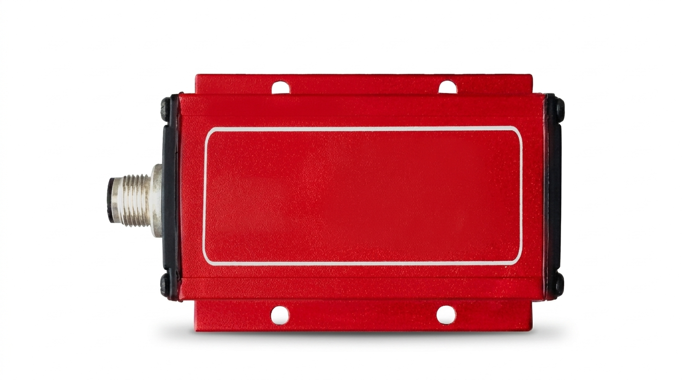
Verify event detection and gap accuracy as separate acceptance tasks.
- Identify the installed track. Record blade layout, physical gap, mounting and component references; agree the safe test envelope with the equipment owner.
- Validate the speed output. Compare with an independent tachometer/reference over minimum/maximum speed and transients. Record missed/extra events and the configured pulse definition.
- Validate the clearance channel. If requested, compare its calibrated result against the agreed representative gap reference across speed, gap and temperature. Retain the raw feature and processing settings.
- Retain configuration and fault records. Confirm load, filtering, sample/trigger settings, sensor-loss behavior and controller output. A wiring test pulse alone does not validate blade detection.
Review a DZ140-style replacement around its actual channel functions.
Send complete original sensor/controller references, blade setting, output mode, wiring and mounting drawings, sensor cable, temperature requirements and DAQ input. The original manufacturer's DZ140 page provides system context. ECS-AUTO / turbo test is an engineering request path; original ratings, temperature output, connectors and calibration do not transfer to a new configuration.
Questions that decide a turbocharger sensing specification
Is blade count the same as output pulses per revolution?
Only if that is the defined and validated output mode. A controller may normalize multiple blade events to one rotation pulse. Confirm detectable events at the installed track and the receiving counter setting.
Can a RAW alignment signal be used directly as clearance?
Its intended function, loading and response must be known. Clearance requires a calibrated relationship and operating-envelope evidence; a diagnostic connector or visible pulse amplitude does not supply that evidence.
Does a 100 kHz sensor guarantee detection at a given RPM?
No. Blade count, tip geometry, gap, transit response, trigger electronics and receiving system all matter. State the operating envelope and validate the complete measurement chain.
Does a temperature limit apply to the sensor cable and controller too?
Use separately documented continuous/peak limits and exposure times for each component, transition and connector. Match the proposed assembly to its actual installation zone.
What should an automotive test lab include in an RFQ?
Include rotor and housing geometry, alloy, detected events, RPM/gap envelope, temperatures, output/DAQ definition and independent acceptance reference. State original references and quantities for a replacement request.
| Decision | Eddy current displacement system | Standard inductive proximity switch |
|---|---|---|
| Measurement | Continuous distance or dynamic motion | Target present / absent |
| Output | Calibrated voltage, current or digital distance | Discrete ON / OFF |
| Specify | Range, resolution at bandwidth, target and calibration | Switching distance, hysteresis and switching frequency |
Analog inductive distance sensors also exist. Compare the actual measurement principle and performance, rather than the category name alone.
ECS-AUTO / TURBO CONFIGURATION REQUEST
Send the rotor, event definition and receiving input in one brief.
Use the optional turbo fields to describe the actual measurement. Request speed detection and dynamic clearance evidence separately when both are needed.